Oil Seal Pressure Limit: Why 30 kPa Is the Practical Ceiling
ISO 6194-1 covers rotary shaft lip seals for low pressure duty, about 0 to 30 kPa above atmospheric. Here is what changes above that, and what to ask for instead.
Oil Seal Pressure Limit: Why 30 kPa Is the Practical Ceiling
ISO 6194-1 covers rotary shaft lip seals for low pressure duty, about 0 to 30 kPa above atmospheric. Here is what changes above that, and what to ask for instead.
Short answer
A rotary shaft lip seal built to ISO 6194-1 is a low pressure device. The scope of the standard describes seals utilising elastomeric sealing elements as suitable for use under low pressure conditions, and the figure the whole document is written around is fluid pressure from 0 to 30 kPa (0.3 bar) above atmospheric, with atmospheric pressure on the air side. That number does not appear as a rating in a table; it is the duty the geometry, the tolerances and the test procedures assume. Above it, three things start at the same time: fluid load adds to the garter spring load at the lip, friction heat climbs, and the heel is pushed toward the nearest clearance. So the useful question is not "what is the maximum pressure" but "which of those three effects appears first in my duty cycle, and what do I change for each one".
What the standard actually says about pressure
ISO 6194 is split into five parts, and none of them contains a pressure rating table:
| Part | Covers | What it gives you on pressure |
|---|---|---|
| ISO 6194-1 | Nominal dimensions and tolerances | The low pressure duty the dimensions assume, plus shaft and bore limits |
| ISO 6194-2 | Vocabulary | Terms, not limits |
| ISO 6194-3 | Storage, handling and installation | Nothing about pressure |
| ISO 6194-4 | Performance test procedures | How a bench test is run, not a rating for your fluid |
| ISO 6194-5 | Identification of visual imperfections | Nothing about pressure |
That table is worth a second look before a purchase order goes out. When a drawing or a catalogue line claims a pressure rating for a lip seal, the number did not come from ISO 6194-1. It came from the manufacturer's own testing, from a test on a similar duty, or from nothing at all. The question to ask is which document the rating comes from and what that document actually measured.
The scope sentence also explains why the limit exists. ISO 6194-1 geometry assumes an interference fit between seal, shaft and housing, and a lip held on the shaft by interference plus a garter spring. Nothing in that arrangement is balanced against a pressure differential. That is also why ISO 16589 exists as a separate standard for rotary shaft lip seals with PTFE sealing elements: thermoplastic lips are used on duties where an elastomer lip is not the right answer in the first place.
Why pressure changes the physics at the lip
The lip is a cantilever. At baseline, its contact load is set by the interference moulded into the part and by the garter spring seated behind the lip. Most of what a standard lip seal does well follows from that load staying small: the contact band stays narrow, friction stays low, and the lubricating film at the contact stays stable.
Fluid pressure loads the lip in one of two directions, and the direction decides the failure mode:
| Pressure acts on | What happens at the lip | What you see in service |
|---|---|---|
| The fluid side, with the lip fitted the normal way | Contact load rises on top of the spring load; friction and contact temperature rise with it | A lip that hardens and wears, then weeps once the contact temperature has climbed |
| The back of the lip, because the seal was fitted backwards or the air side became the wet side | The load lifts the lip edge off the shaft | Weeping from the first hours of running |
| A cavity between two lips that has no way to vent | Trapped pressure pushes on both contacts | Leakage at whichever lip has the weaker contact |
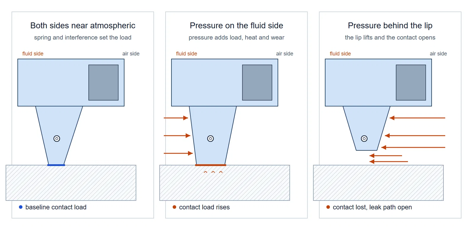
The first row is the one buyers underestimate, because it does not look like a pressure problem. A seal running at triple its design contact load still seals on the test bench. It seals while the contact temperature climbs, while the elastomer hardens, and while the wear flat grows, and then it leaks months later with no obvious cause. When a failed lip comes back hardened and worn across a wide band, pressure loading is one of the first things to rule out, along with the shaft surface and the fluid temperature.
The pressure most housings see does not come from the process
A gearbox or an axle rarely has a process pressure. What it does have is trapped air and oil that heat up and cool down:
| Cause | Direction | Typical trigger |
|---|---|---|
| Air and oil expand as the unit warms up | Positive | Long duty cycles, high ambient temperature, heat soak after shutdown |
| Hot air contracts fast | Negative | Cold water wash or sudden weather change on a hot housing |
| Gears throw oil at the seal | Positive, pulsed | High speed, overfilling, wrong oil level |
| Breather blocked by mud, paint, grease or ice | Either | Service that cleans the machine but not the vent |
A lip seal sees all of that. Housing pressure that never had to exist is the easiest pressure to remove, and it is the only item on this page that maintenance can fix without touching the seal. Before specifying anything for pressure, check the breather path along its whole length, check the oil level against the specified condition, and check whether the housing has any vent at all.
What to change when the pressure is genuinely higher
Once the housing is vented and the pressure is still real, work down this list:
| Change | What it does | Watch out for |
|---|---|---|
| Vent or breather sized for the duty | Removes pressure that should never reach the lip | The vent opening has to stay protected from dirt and water |
| Tighter clearances: bore to H8, shaft to h11 | Less room for elastomer to be pushed into | Assembly still has to be possible on the line |
| Shorter flex section or a thicker heel | More material behind the lip edge to resist being pushed | A stiffer lip changes running temperature and follow behaviour |
| Rigid ring behind the heel | Blocks the extrusion path with a hard shoulder | The ring has to be located and held, not floating in the cavity |
| A different sealing principle: PTFE lip seal to ISO 16589, a cassette seal, or a mechanical face seal | The design carries the pressure load instead of the elastomer | Different leakage behaviour, different fitting practice, different shaft preparation |
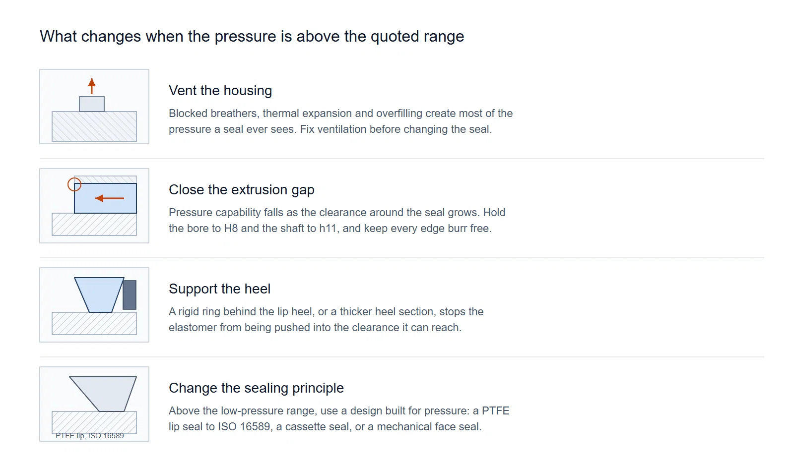
Two of those rows deserve a comment. First, tightening clearances is the change most often skipped, because it costs the machine builder a tolerance review rather than a new part. Second, a stronger garter spring is not on the list on purpose. Extra spring load does press the lip harder onto the shaft, but it also raises baseline friction and heat, and it does nothing about the heel being pushed toward a clearance. On a duty that is already hot, more spring load usually moves the failure earlier, not later.
What to ask when a supplier quotes a pressure figure
A pressure claim is only as good as the test behind it. Before accepting a rating, ask:
- Which test procedure was followed, and was it a standard bench procedure or an application test
- At what gauge pressure, for how many hours, and at what fluid temperature
- On what shaft diameter, surface speed and eccentricity was it run
- What did the lip look like afterwards, and is that documented in a test report
- Whether the quoted figure is a continuous rating or a peak that the duty cycle only touches occasionally
A test report with real numbers on it answers more questions than any rating on a price list. It is also the document that lets your own engineers judge how far the test duty is from yours, which is the judgement that actually matters.
What to put on your drawing
The pressure question is a specification question, and it belongs on the drawing:
- Normal and transient gauge pressure at the seal, separately stated
- Fluid, oil level relative to the seal, and temperature at the lip, not just in the sump
- Shaft diameter, speed range and expected runout
- Housing vent or breather provision, drawn as a feature rather than left to the shop
- Shaft and bore limits consistent with ISO 6194-1: shaft not coarser than h11 to ISO 286-2, bore not coarser than H8, surface finish in the Ra 0.2 to 0.5 µm band, and shaft hardness at least 30 HRC, or 45 HRC where handling damage is a risk
Questions buyers ask us
Is 30 kPa a hard limit?
No. It is the duty range that ISO 6194-1 was written around, and it is the range the convenor of the ISO working group behind these standards quotes for them: atmospheric pressure on the air side and fluid from 0 to 30 kPa above atmospheric. Seals do run above it, in designs and shaft arrangements made for the load. What the figure tells you is where the standard geometry stops being the default answer and starts being a decision that needs data.
Can a stronger garter spring fix a pressure problem?
Rarely. Spring load adds to the contact load that pressure is already adding to, which raises heat at the contact. A pressure problem is a load and clearance problem, and the fixes are ventilation, tighter clearances, a supported heel or a different sealing principle.
Should the lip face the pressure?
The lip and the garter spring face the fluid being retained. Fitted that way, fluid pressure presses the lip onto the shaft. Fitted the other way, the same pressure acts on the back of the lip and lifts it off, which is why a reversed seal can weep from the first hour. If your arrangement puts pressure on the outboard side, that has to be stated, because it changes which design is appropriate.
Does a double lip seal hold more pressure?
No. The second lip excludes dust and splash. It is not a pressure stage, and pressure trapped between two lips without a vent path becomes its own problem. Pressure capability comes from the load path and the clearances, not from the number of lips.
What should I measure before asking for a replacement seal?
Gauge pressure at the seal, or the closest thing to it: the temperature the housing reaches, the duty cycle, the oil level, and whether the breather is clear. A failed seal tells you the contact got hot; those five items tell you why.
Put the pressure question on the drawing
Most pressure problems with lip seals are specification problems that showed up late. The standard that defines the seal, the shaft and the housing assumes a low pressure duty, and it says so in its scope. Everything above that range is an engineering decision that someone has to own: the vent, the clearances, the heel support or the change of sealing principle. Write the pressure, the temperature and the duty cycle on the drawing, and the conversation with any seal supplier starts from data instead of from a catalogue line.
- Standards referenced in this article: ISO 6194-1, ISO 6194-2, ISO 6194-3, ISO 6194-4, ISO 6194-5, ISO 16589, ISO 286-2.
Related catalog and engineering resources
Compare the general rotary shaft seal catalog against the complete drawing and operating conditions. Material names alone do not establish a pressure rating. Consult the rotary shaft seal technical manual for general selection guidance and the replacement checklist before requesting a part-specific drawing review.
Need help specifying a seal?
Use these checks to prepare your enquiry. Final suitability depends on the specific design and operating conditions.
Check dimensions and design
Provide the shaft diameter, housing bore and seal width in mm. Include the part marking, lip profile or a dimensioned drawing if available.
Describe operating conditions
Share the fluid or medium, operating temperature, pressure and shaft speed. Confirm the material grade against the application.
Verify a replacement
Provide the original part number and photos. Similar dimensions alone do not confirm interchangeability; compare the design and material.