Oil Seal Visual Defects: Reading the ISO 6194-5 Critical Area
ISO 6194-5 names 14 imperfection types and sizes the sealing lip critical area by x and y, but it sets no accept limits. Here is what a buyer has to add.
Oil Seal Visual Defects: Reading the ISO 6194-5 Critical Area
ISO 6194-5 draws a critical band around the sealing edge and names 14 imperfection types, but it sets no accept limits. Here is what a buyer has to add.
Short answer
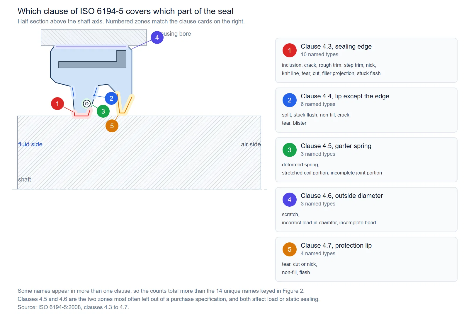
ISO 6194-5 is a locating and naming document, not an acceptance specification. It does two things. It defines a sealing lip critical area sized by two dimensions, x and y, which scale with shaft diameter (clause 4.1 and Table 1). It also gives a name and a reference illustration for each of 14 surface imperfection types, sorted into five zones of the seal: the sealing edge (clause 4.3), the rest of the lip (4.4), the garter spring (4.5), the outside diameter (4.6) and the optional protection lip (4.7). It does not say how large an imperfection may be before a part is rejected. The scope states that the document is "intended as a convenience for purchasers and manufacturers in their discussions concerning the importance of these imperfections in different applications", and the note to Table 1 adds that these are typical values and that "specific values shall be agreed to between purchasers and suppliers". A purchase line reading only "visual imperfections to ISO 6194-5" therefore buys shared vocabulary, not a reject rule.
The critical area is about 1.2 mm wide, so most of the seal is not critical
This is the part that changes how an incoming inspection argument goes.
| Shaft diameter d1 | x, mm | y, mm |
|---|---|---|
| d1 up to 50 | 0.6 | 1.2 |
| above 50 up to 120 | 0.8 | 1.5 |
| above 120 | 1.0 | 2.0 |
Values: ISO 6194-5:2008, Table 1. The standard marks them as typical and requires the values used on a specific order to be agreed between purchaser and supplier.
x and y are the two legs of the band, both measured from the sealing edge along the lip surface, and y is always the longer leg. Clause 4.1 gives the reason they were chosen: "in cases of wear, imperfections in this area can impair the function of the rotary-shaft lip-type seal during its lifetime". The boundary is a wear argument rather than an appearance argument. The band marks how far the contact line can retreat as the lip wears before a flaw sitting further back becomes a leak path.
Two consequences follow in practice. A flaw outside the band is a different class of finding from one inside it, and the standard gives you the millimetres to say which. The band also widens with shaft size, so an inspection written for a 40 mm shaft does not transfer to a 150 mm shaft without reading Table 1 again.
Two vocabularies exist, and mixing them starts arguments
Worth knowing before you quote an old drawing. The first edition, ISO 6194-5:1990, called the same concept the "area of sealing edge" and keyed the surfaces in its Figure 1 as LFF (lip front face), LBF (lip back face) and SE (sealing edge). The current edition, ISO 6194-5:2008, calls it the "sealing lip critical area" and keys the surfaces as lip fluid side (1), sealing edge (2), lip air side (3) and optional protection lip (4). The x and y values did not change between the two editions. If a supplier drawing still uses front face and back face language, the numbers behind it are the same and only the labels moved.
ISO 6194-5:2008 is edition 2. It was confirmed at stage 90.93 after the systematic review closed in 2022, so it is the version to cite.
The 14 names and the clause that owns each zone
| Zone of the seal | Imperfections named there | Clause |
|---|---|---|
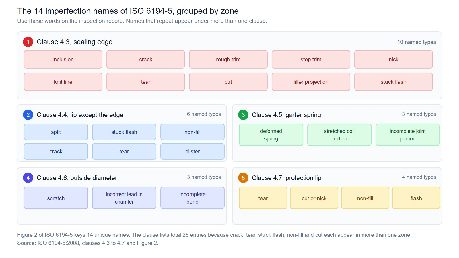
| Sealing edge | inclusion, crack, rough trim, step trim, nick, knit line, tear, cut, filler projection, stuck flash | 4.3 |
| Lip, except the sealing edge | split, stuck flash, non-fill, crack, tear, blister | 4.4 |
| Garter spring | deformed spring, spring with stretched coil portion, spring with incomplete joint portion | 4.5 |
| Outside diameter | scratch, incorrect lead-in chamfer, incomplete bond | 4.6 |
| Optional protection lip | tear, cut or nick, non-fill, flash | 4.7 |
The counts add up to more than 14 because several names appear in more than one zone. Crack is listed in 4.3 and 4.4, tear in 4.3, 4.4 and 4.7, non-fill in 4.4 and 4.7, and stuck flash in 4.3 and 4.4. Figure 2 of the standard keys 14 unique names in total.
What each name means on the part
| Name | What you are looking at |
|---|---|
| Inclusion | Foreign material, filler or flash pressed into the lip. The standard illustrates three variants: flash, filler and foreign material |
| Nick | A small notch broken out of an edge |
| Step trim | A step or shelf left where the trimming cut did not meet cleanly |
| Tear | A separation with torn surfaces |
| Crack | A linear break in the elastomer, at the surface or into the body |
| Rough trim | An irregular surface left by the trimming operation |
| Knit line | The line where two flow fronts met during moulding |
| Stuck flash | Flash that stayed attached instead of being removed |
| Cut | A slit with clean edges, usually traced to a blade or a sharp handling edge |
| Filler projection | A filler particle standing proud of the surface |
| Non-fill | Material missing because the cavity did not fill |
| Blister | A raised bubble at or under the surface |
| Split | The body opened along one direction |
| Flash on optional protection lip | Flash remaining on the auxiliary lip |
The value of this table is procedural. Once both sides use the same word for the same feature, the remaining question is only whether that feature may be present and how large it may be, which is a commercial question rather than a vocabulary question.
Sealing edge versus the rest of the lip
Clause 4.3 covers what sits on the sealing line itself. Clause 4.4 covers the same lip away from that line. The same three words (crack, tear, stuck flash) appear in both clauses, and the zone decides why the finding matters.
On the sealing edge, a flaw sits inside the band that becomes the contact line as the lip wears. Away from the edge, the same flaw sits in material that carries load and keeps the lip geometry stable. Both are worth recording, and they are worth recording separately, because a limit set for one zone does not automatically apply to the other.
This separation also protects you from an over-wide rejection. A moulding knit line on the outside face of the lip body is a real observation, and clause 4.4 gives it a name, but it is not the same finding as a knit line crossing the sealing edge.
Spring and outside diameter: the two clauses buyers rarely quote
Clause 4.5 is the only place in this part of ISO 6194 that deals with the garter spring, and it names three conditions: deformed spring, spring with stretched coil portion and spring with incomplete joint portion. None of the three is cosmetic. The spring contributes the radial load that holds the lip against the shaft, so a stretched coil and a joint that did not close change how the seal loads the shaft.
That connects directly to ISO 6194-4. Clause 4.3 of ISO 6194-4 requires the lip diameter to be measured with the spring in place, precisely because the spring belongs to the measured lip. When you specify a lip diameter check, specify that it is done with the spring fitted.
Clause 4.6 covers the outside diameter and names scratch, incorrect lead-in chamfer on the seal outside diameter and incomplete bond. The last two are the only entries in the whole document that are really about static sealing and assembly rather than about surface appearance. An incomplete bond between the elastomer body and the metal insert opens a path along the insert, and the wrong chamfer on the seal outside diameter can shave rubber during pressing. Both sit in the static contact that retains the seal in the bore and blocks leakage around the outside.
What ISO 6194-5 deliberately does not give you
Four things sit outside this document, and each one is a reason why a bare "to ISO 6194-5" note is hard to enforce.
- No accept or reject sizes. The scope is written as a discussion aid for purchasers and manufacturers. There is no table of maximum flaw dimensions anywhere in the nine pages.
- No sampling plan. ISO 6194-5 does not tell you how many parts to examine. Sampling is a separate matter. ISO 2859-1 defines acceptance sampling by attributes, and an AQL in that system is a statistical risk level, not a statement that no nonconforming part can be present in a lot.
- No magnification, lighting or viewing distance. Nothing in the standard fixes how the surface is lit or how close the eye or the camera gets. Two inspectors at two benches can record the same part differently, which is exactly the disagreement the shared vocabulary is meant to end. Set magnification, lighting, viewing distance and the decision rule in your own document.
- No performance correlation. The standard names and locates. It does not say how many running hours a given nick costs you. ISO 6194-4 is the part that covers performance test procedures.
The third point is where most disputes are actually lost. Without viewing conditions fixed in writing, the argument is not about the part. It is about the bench.
Turning the vocabulary into something enforceable
Work through these in order when you write the inspection requirement:
- Name the zones. For most rotary shaft lip seals that means 4.3 and 4.4, plus 4.5 and 4.6 if you want the spring and the outside diameter covered.
- Fix x and y for your shaft diameter from Table 1, and write the millimetres down. Do not write "critical area per ISO 6194-5" without them.
- Give each imperfection a size limit in your own units, or state that a named type is not permitted inside the critical area at all.
- State how the part is examined: magnification, lighting, viewing distance, and whether the lip is spread during the examination.
- State the sample. Reference ISO 2859-1 with an AQL and an inspection level, or agree a fixed count per lot, and say what happens on a borderline finding.
- Ask for the clause 5 identification statement in the paperwork, with the lot number next to it.
Clause 5 is short enough to quote in full. It recommends that manufacturers use this statement in test reports, catalogues and sales literature when electing to comply:
"Visual imperfection identification is in accordance with ISO 6194-5, Rotary-shaft lip-type seals incorporating elastomeric sealing elements - Part 5: Identification of visual imperfections."
Read that sentence carefully when it appears on a test report. It is a statement about how imperfections are identified. It is not a statement that a lot passed anything.
Failure modes and the zone to inspect first
| Field complaint | Inspect this first | Clause or document |
|---|---|---|
| Leaks from the moment it is fitted | Sealing edge | 4.3 |
| Leak that starts after running in | The band around the edge, sized by x and y for your shaft | 4.1 and 4.3 |
| Lip rolled or flipped during fitting | Lead-in chamfer on the seal outside diameter, and fitting practice | 4.6 and ISO 6194-3 |
| Leak around the outside of the seal | Outside diameter: scratch, incorrect chamfer, incomplete bond | 4.6 |
| Lip not tracking the shaft, low radial load | Spring geometry | 4.5 |
| Seal rotates in the bore | Outside diameter condition and bore tolerance H8 per ISO 6194-1 | 4.6 and ISO 6194-1 |
| Dirt reaching the main lip | Protection lip condition | 4.7 |
| Surface breaking up in storage | Storage conditions | ISO 6194-3, not covered here |
Questions buyers ask us
Does ISO 6194-5 tell me whether to reject a part?
No. It names imperfections and says where they occur. Limits come from your drawing or the inspection document that goes with it. Even the values in Table 1 are marked as typical and need agreement between purchaser and supplier.
Is the sealing edge the same thing as the sealing lip?
Not in this document. Figure 1 keys the lip fluid side and the lip air side as separate surfaces with the sealing edge between them, then defines a critical band around that edge using x and y. Clause 4.3 concerns the edge, and clause 4.4 concerns the lip away from the edge.
Can a part have an imperfection outside the critical area and still matter?
Yes, depending on where it is. Clause 4.6 puts incomplete bond and incorrect outside diameter chamfer far from the lip, and both affect the static seal at the bore. Some findings matter because of the zone they sit in rather than because they fall inside x and y.
Which standard covers PTFE lip seals?
The ISO 16589 series covers seals with thermoplastic sealing elements, and ISO 16589-5 is the part dealing with visual imperfections. ISO 6194-5 itself notes that ISO 6194 (all parts) is complementary to ISO 16589 (all parts).
Where does the 0.6 mm figure come from?
Table 1 of ISO 6194-5, for shaft diameters up to and including 50 mm. It is the x dimension, the shorter of the two legs of the critical band. The pair rises to 0.8 and 1.5 mm above 50 mm, and to 1.0 and 2.0 mm above 120 mm.
Do I need ISO 6194-5 if I already specify ISO 6194-4?
They answer different questions. ISO 6194-4 covers performance test procedures and the values declared for a batch, such as hardness, density, compression set and mass change after immersion. ISO 6194-5 covers what you can see on an individual part. A batch can meet its declared values and still contain parts with a nicked sealing edge.
Writing it back into your own drawing
Put three things on the drawing or in the inspection document that accompanies it: the zones you care about, the x and y values for your shaft diameter taken from Table 1, and a size limit per imperfection name. Add the examination conditions and the sampling rule beside them. Reference the storage, handling and installation guidance of ISO 6194-3 alongside, because some findings are made at fitting rather than at moulding.
Once those are written down, the clause 5 sentence becomes something you can actually check. You can ask whether the identification was carried out as described, instead of arguing about what a compliance claim was supposed to mean.
Documents referenced in this article: ISO 6194-1, ISO 6194-2, ISO 6194-3, ISO 6194-4, ISO 6194-5, ISO 16589-1, ISO 16589-5, ISO 2859-1, ISO 5598.
Need help specifying a seal?
Use these checks to prepare your enquiry. Final suitability depends on the specific design and operating conditions.
Check dimensions and design
Provide the shaft diameter, housing bore and seal width in mm. Include the part marking, lip profile or a dimensioned drawing if available.
Describe operating conditions
Share the fluid or medium, operating temperature, pressure and shaft speed. Confirm the material grade against the application.
Verify a replacement
Provide the original part number and photos. Similar dimensions alone do not confirm interchangeability; compare the design and material.