Oil Seal Tandem Arrangement: What Two Seals in One Bore Need
An oil seal tandem arrangement puts two lips in one bore. ISO 6194-1 clause 6.1 caps pressure at 30 kPa; no clause in the series says what goes between them.
Oil Seal Tandem Arrangement: What Two Seals in One Bore Need
An oil seal tandem arrangement puts two lips in one bore. ISO 6194-1 clause 6.1 caps pressure at 30 kPa; no clause in the series says what goes between them.
Short answer
An oil seal tandem arrangement is two complete rotary shaft lip seals fitted one behind the other in a single bore, with a cavity between them. ISO 6194-1:2007 sizes a bore for one seal. Table 3 sets the bore depth at the seal width plus 1.2 mm where the width is 10 mm or less, or plus 1.5 mm above that, and clause 6.1 puts the sealed pressure at 0 kPa to 30 kPa above atmosphere. Nothing in the ISO 6194 series defines the cavity, its grease fill, its vent path or the orientation of the second seal. All four belong on your drawing, because they decide whether the pair outlasts a single seal or fails sooner than one.
One standard family has a word for this and the other does not
Mechanical seals are sorted along four axes in API 682, and arrangement is one of them. Arrangement 1 is a single seal. Arrangement 2 puts two seals in one cartridge with a chamber between them held below seal chamber pressure. That chamber gets a liquid buffer, a gas buffer or nothing at all. The trade calls the result a tandem seal. Arrangement 3 fills the same chamber with a barrier fluid held above process pressure, which is what a double seal means.
Why two words for one chamber? A buffer sits below the process pressure and dilutes leakage. Barrier fluid sits above it by design, keeping process fluid off the outboard seal.
Lip seals get no such axis. Clause 5 of ISO 6194-1:2007 illustrates four outside diameter constructions plus the common lip layouts, one of them a single lip with a protection lip. Clause 6 covers pressure and nominal dimensions, while clause 8 deals with the housing. Every clause in the series is written for one seal in one bore, so a pair has no vocabulary to be specified in.
That gap carries a price. On a pump datasheet, arrangement 2 is enough for every bidder to picture the same chamber. A two-seal lip arrangement has no equivalent shorthand, so the cavity condition gets settled on the shop floor instead.
What clause 6.1 already caps
Clause 6.1 of ISO 6194-1:2007 puts these seals at 0 kPa to 30 kPa gauge with atmospheric pressure on the air side, and directs the user to the manufacturer above that. At 0.3 bar the ceiling sits low enough that plenty of ordinary hardware crosses it without anybody noticing.
Catalogue figures run higher. One widely circulated seal catalogue rates standard types at 0.5 bar up to 1000 r/min and 2.8 m/s, at 0.35 bar up to 2000 r/min and 3.15 m/s, and at 0.2 bar up to 3000 r/min and 5.6 m/s. Those numbers and clause 6.1 differ by a factor near 1.7 at the slow end. Either figure can go on a drawing, provided it is written down. A pair makes the question unavoidable, because the space between the two lips develops a pressure of its own.
The cavity nobody specifies
Take a 60 mm shaft in an 80 mm bore with 8 mm between the two lips. The annulus holds 17.6 cm³. Fill it to two thirds with grease, the figure one catalogue gives when the medium lubricates poorly. Some 11.7 cm³ of grease then sits above 5.9 cm³ of air at 20 °C.
Heat that assembly by 40 K and the grease grows by about 0.33 cm³. The air space shrinks. The air warms at the same time. Gauge pressure lands near 20 kPa. Heat it by 80 K instead and the same cavity reaches about 42 kPa. Both results follow from P₂ = P₁ × (V₁ / V₂) × (T₂ / T₁), with V₂ taken as the air volume left after the grease has expanded, and any spreadsheet reproduces them.
| Cavity condition | Gauge pressure reached | Where that leaves you |
|---|---|---|
| Two thirds grease, 40 K rise | about 20 kPa | Inside the 30 kPa of clause 6.1 |
| Two thirds grease, 80 K rise | about 42 kPa | Above clause 6.1; below 0.5 bar at 1000 r/min |
| Filled to the brim, rigid cavity, 80 K | about 84 MPa | No lip seal cavity is rigid, so something gives |
Filling the space completely is a different problem. With no air left to compress, pressure rise follows ΔP = α × B × ΔT. Here α is the volumetric expansion coefficient; B is the bulk modulus. Mineral oil sits near 7 × 10⁻⁴ K⁻¹. Its bulk modulus runs from 1.5 GPa to 1.8 GPa over normal working temperature. Fifty degrees of heating at 7 × 10⁻⁴ K⁻¹ and 1 GPa returns 35 MPa in a rigid volume. Eighty degrees at 1.5 GPa returns 84 MPa.
Real cavities are not rigid. What gives way is the lip, which lifts and lets the cavity discharge. It may equally be the rubber membrane, since one catalogue warns that a chamber packed full will force grease between the membrane and the metal case.
Bore depth: Table 3 fits one seal
Table 3 of ISO 6194-1:2007 gives the bore depth as the seal width plus a clearance, b + 1.2 mm for widths up to 10 mm and b + 1.5 mm above that. Two 10 mm seals with an 8 mm gap between them need 29.2 mm of bore, against 11.2 mm for a single seal of the same width.
Width tolerance widens the stack. ISO 6194-1 clause 9.1 allows ±0.3 mm on narrow seals and up to ±0.6 mm on wider ones, so a nominal 20 mm of seal can measure 21.2 mm. Cavity length carries no tolerance anywhere in the standard, since the standard does not know the cavity exists. Give it a dimension and a tolerance, or the second seal ends up seated against the first.
Three orientations, three jobs
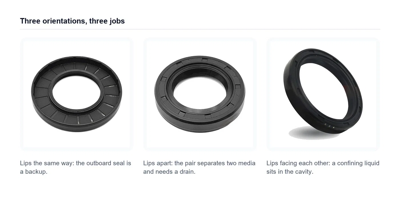
Lips pointing the same way make the outboard seal a backup for the inboard one. Both retain the same fluid, and the outer lip runs on whatever lubricated it during assembly.
Lips facing apart suit a pair that separates two media. Catalogues recommend a drain or leakage bore in the space between so neither side can pressurise the cavity, and a bearing seal patent describes the same thing, a passage running from the cavity out to atmosphere.
Lips facing each other suit a cavity filled with a confining liquid. The inner seal then carries pressure from the cavity side rather than from the sump.
Direction compounds the problem when either seal carries a hydrodynamic aid. ISO 6194-2:2009 supplies the vocabulary for such a feature and covers uni-directional and bi-directional forms, yet nothing on the outside of a seal marks the way it pumps. Two helical lips in one bore have to pump the same way.
The outer lip runs on whatever you put there
The inboard seal sees the sump. The outboard seal sees grease, and grease carries frictional heat away far less well than oil. One catalogue restricts the permissible circumferential speed by about 50 % under grease lubrication; a second one limits grease duty to slowly rotating shafts altogether. A 60 mm shaft at 1000 r/min runs 3.14 m/s, so the outboard lip needs that derating applied to whatever speed figure the catalogue quotes for oil.
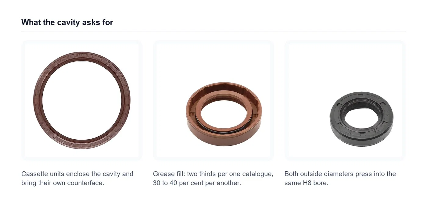
Fill fraction splits the sources. Two catalogues cap it at two thirds of the space, and a third publication puts it at 30 % to 40 % for the same cavity. Nobody should be surprised by a spread that wide, because the fraction trades lubrication of the outer lip against pressure rise inside the cavity. Both agree on leaving room and on providing a way to add grease later.
What a test report cannot cover
ISO 6194-4 sets out a performance test procedure for one seal at a time. Its clause 5.1 fixes the oil level at 0.3 d1 to 0.5 d1 above the lowest point of the shaft, with at least 750 cm³ in the rig. Six seals then run for 240 h under clause 6.1. Any report written to that standard says nothing about a cavity, a vent path or a second lip 8 mm away. Asking a supplier for an arrangement test is reasonable, and it is outside the standard, so the order has to say so.
What to write on the drawing and the order
- Bore depth and cavity length as two separate dimensions, each with a tolerance;
- Orientation of both seals, drawn in section rather than described in words;
- Cavity fill: grease specification; fill fraction; how grease gets there later;
- Drain or vent: present or absent, plus where it discharges;
- Shaft finish across the whole length that both lips traverse, at Ra 0.2 µm to 0.5 µm and Rz 1.2 µm to 3.0 µm measured axially, with 30 HRC or 45 HRC where handling damage is likely;
- Axial retention for whichever seal can see pressure, by housing shoulder, distance ring or retaining ring;
- Whether either seal carries a hydrodynamic aid and which way it pumps.
Two press fits into one bore also change the fitting sequence. ISO 6194-3 clause 7.5 asks for a press tool; clause 7.6 for locating the seal against a machined face; clause 7.11 for a lubricated outside diameter driven at a steady rate. The second seal has to be driven past the first, so the tool has to reach it without touching the lip already in place.
Two ways a pair fails
| What you see | What the cavity did | What it tells you |
|---|---|---|
| Grease pushed past the outboard lip; membrane lifted off the case | Pressure rose with temperature | Fill fraction too high, or no vent path |
| Outboard lip hard and cracked while the inboard lip stays soft | Outer lip ran with no lubricant | The pair worked as one seal from the day it was built |
| Inner seal found out of its bore | Cavity pressure pushed it back | No shoulder or retaining ring behind it |
Does a second seal raise the pressure rating?
No. ISO 6194-1 clause 6.1 puts the seal type at 0 kPa to 30 kPa. That cavity generates pressure rather than removing it. Above 30 kPa the standard hands you to the manufacturer, and the cavity condition is the first thing that manufacturer will ask about.
Can the cavity be packed full of grease?
Not according to the sources. One catalogue states that filling the grease chamber completely builds pressure and forces grease between the membrane and the metal part. Two thirds is the figure given elsewhere, and 30 % to 40 % appears in a third publication.
Should both seals face the same way?
That depends on which of the three jobs the pair does. Retaining one fluid calls for the same direction. Separating two media calls for lips facing apart with a drain between them. A confining liquid in the cavity calls for lips facing each other.
Is a cassette seal the better answer?
For heavy dirt, one catalogue points to cassette seals. Such a unit is fully enclosed. Several protective lips surround a grease-filled labyrinth, and the counterface comes inside the unit. That last item removes the shaft finish question from your drawing. It also moves the assembly outside the bore geometry of ISO 6194-1, because the running surface travels with the seal.
What should a buyer ask a supplier for?
Ask for three separate items. First, a dimensional test report per batch under ISO 6194-4 clause 4.2. Second, the cavity conditions in writing. Third, the orientation drawn on the order line. Where a hydrodynamic aid is fitted, ask for the pumping direction and the shaft size it was measured on. Clause 5.1 runs the rig on one of five shaft diameters, so the number means little without knowing which.
- Standards referenced: ISO 6194-1:2007 (clauses 5, 6.1, 7.3, 8.1 and Table 3, clause 9.1); ISO 6194-2:2009 (vocabulary, hydrodynamically aided seals); ISO 6194-3 (clause 7); ISO 6194-4 (clauses 4.2, 5.1, 6.1); ISO 6194-5:2008; ISO 21049:2004; API 682, 4th edition (arrangements 1 to 3); ISO 286-2 (h11, H8); ISO 16589-1:2011 (Annex A).
Need help specifying a seal?
Use these checks to prepare your enquiry. Final suitability depends on the specific design and operating conditions.
Check dimensions and design
Provide the shaft diameter, housing bore and seal width in mm. Include the part marking, lip profile or a dimensioned drawing if available.
Describe operating conditions
Share the fluid or medium, operating temperature, pressure and shaft speed. Confirm the material grade against the application.
Verify a replacement
Provide the original part number and photos. Similar dimensions alone do not confirm interchangeability; compare the design and material.