Shaft Surface Lead: Why a Ra 0.4 µm Journal Still Leaks
ISO 6194-1 sets Ra 0.2 to 0.5 µm on the seal contact surface and adds a line many drawings drop: that surface shall be free of machining lead.
Shaft Surface Lead: Why a Ra 0.4 µm Journal Still Leaks
ISO 6194-1 sets Ra 0.2 to 0.5 µm on the seal contact surface and adds a line many drawings drop: that surface shall be free of machining lead.
Short answer
Shaft surface lead is the shallow helix that grinding, turning or polishing leaves on the seal contact track. ISO 6194-1 clause 7.3 asks for a ground shaft surface of Ra 0.2 to 0.5 µm and Rz 1.2 to 3.0 µm, measured in the axial direction, and states that the seal contact surface shall normally be free of machining leads. A lead is not a roughness defect. It is a direction, and a groove lying at an angle to the shaft axis works as a screw: oil sitting in it is driven along the shaft as the shaft turns. When the helix runs with the rotation and points out of the housing, the surface carries fluid past the lip faster than the lip can return it, and the seal drips. Ra can sit inside the ISO 6194-1 band on a journal that leaks, because roughness parameters describe height while lead describes orientation. The two are specified on the drawing and inspected at the shaft as separate requirements.
A groove at an angle to the axis behaves as a screw
Every machining or polishing operation leaves a residual pattern. Grinding marks, tool feed marks and belt marks are all grooves. If those grooves run around the circumference, square to the shaft axis, they hold oil in place and help keep a film under the lip. If they run at an angle, the same grooves transport fluid along the axis while the shaft turns.
Direction decides which way the fluid moves:
- Helix running with the rotation, opening toward the air side: fluid is carried out past the lip. This is a slow leak that continues while the shaft turns.
- Helix running with the rotation, opening toward the fluid side: fluid is pushed back into the housing, which sounds safe but strips the lubricating film, so the lip runs hot and wears quickly.
The lip itself is a pump. Its contact line is not symmetric, and the form of the lip returns a small amount of fluid to the sealed side on each revolution. The seal tolerates a small helix because the lip out-pumps it. Leakage begins when the transport capacity of the shaft surface exceeds the return capacity of the lip. This is why the same seal design can run dry in one gearbox and drip in another: the difference is often the grinding setup rather than the seal.
What ISO 6194-1 clause 7.3 asks for
| Requirement | Value | Source |
|---|---|---|
| Shaft diameter tolerance | not coarser than h11 | ISO 6194-1, with reference to ISO 286-2 |
| Contact surface roughness, measured axially | Ra 0.2 to 0.5 µm, Rz 1.2 to 3.0 µm | ISO 6194-1 clause 7.3 |
| Machining lead | the seal contact surface shall normally be free of machining leads | ISO 6194-1 clause 7.3 |
| Surface condition | no scratches, scores, pores or spiral machining marks | ISO 6194-1 clause 7.3 |
| Shaft hardness | 30 HRC minimum, 45 HRC where handling damage is likely | ISO 6194-1 |
| Bore diameter tolerance | not coarser than H8 | ISO 6194-1, with reference to ISO 286-2 |
| Who fixes the finish | the surface producer and the seal supplier agree the roughness requirement | ISO 6194-1 clause 7.3 |
Two things in this table matter to a buyer.
The first is that the standard writes the lead requirement as a condition, not as a number: the surface shall normally be free of machining leads. It does not publish a lead angle limit. The number that circulates in sealing practice comes from shaft finishing guides and service bulletins, which place the limit at 0° ± 0.05°. The same figure appears in crankshaft journal guidance from engine rebuilders, in radial shaft seal technical guides from seal distributors, and in metrology articles on lead measurement. It is the working limit the industry applies, and it is not a clause of ISO 6194-1.
The second is the agreement sentence. ISO 6194-1 accepts that not every finishing process can hold Ra 0.2 to 0.5 µm, and it places responsibility for agreeing an alternative finish on the surface producer and the seal supplier. A purchase order that names only the standard is therefore incomplete on the one point that causes most shaft related leakage.
Three finishing routes, three different answers
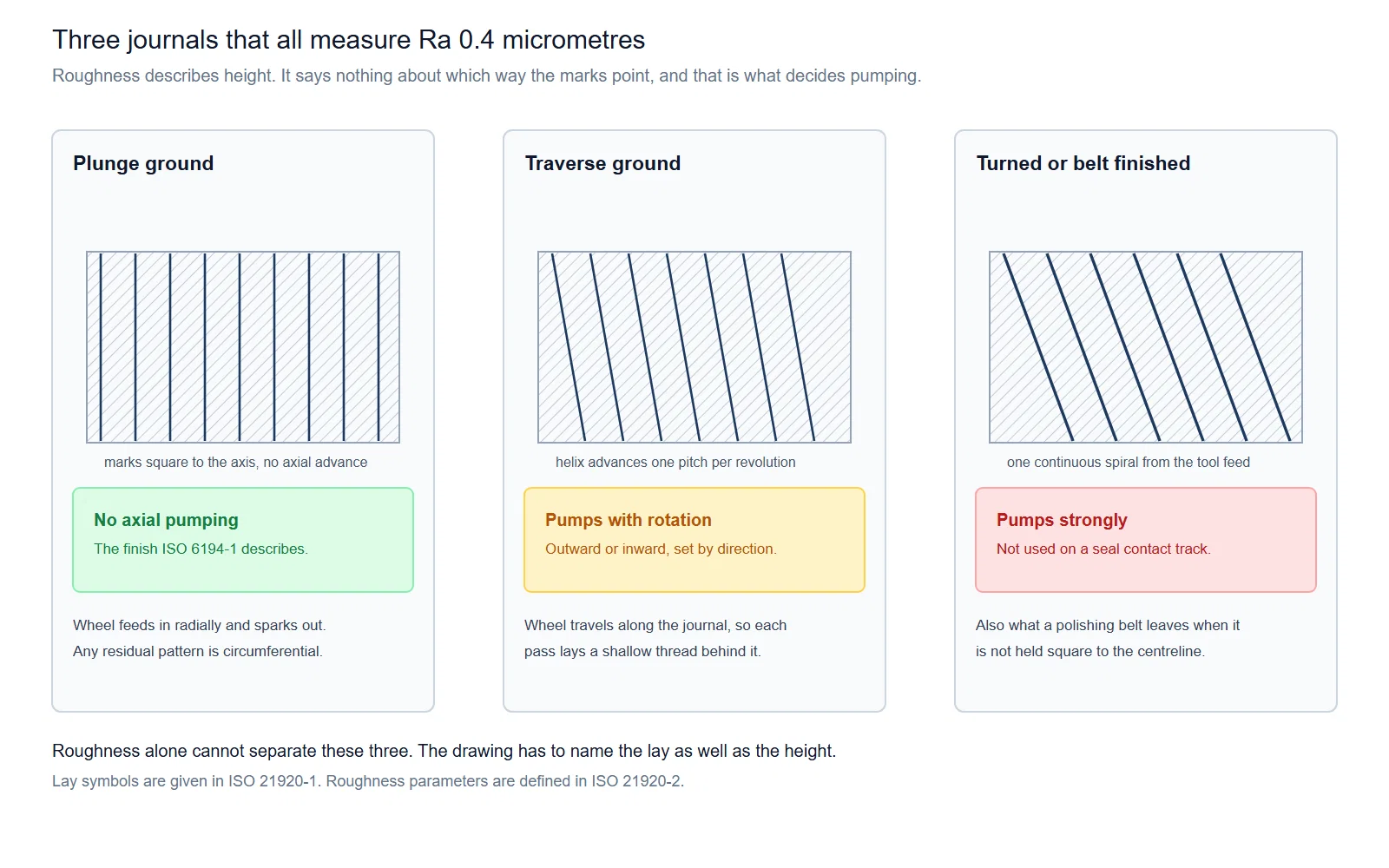
| Process | Shape of the residual marks | Lead risk |
|---|---|---|
| Plunge grinding, ground to spark out | marks square to the axis | none, the route ISO 6194-1 describes |
| Traverse or through feed grinding | shallow helix, one turn of pitch per revolution | present, and it scales with feed rate |
| Turning, including hard turning | one continuous spiral from the tool feed | strong, avoid on a seal track |
| Belt or hand polishing | spiral whenever the belt is not held square to the centreline | present, and easy to introduce on a finished part |
Plunge grinding is the route that produces the surface the standard describes. The wheel feeds radially at a stationary axial position, so the marks it leaves lie in the circumferential direction. Traverse grinding moves the wheel along the journal as it cuts, so every revolution adds a small axial step, and the accumulated step is a thread.
The difference is visible in the finish and invisible in the Ra number. A plunge ground journal and a traverse ground journal can both report Ra 0.4 µm. Only the direction of the marks separates them, which is why the lay symbol belongs on the drawing next to the height value.
Two machine settings that decide whether a helix appears
Plunge grinding removes lead only if two settings are held.
Wheel speed to work speed ratio. If the ratio of grinding wheel revolutions to shaft revolutions is a whole number, the same point on the wheel meets the same point on the shaft on every revolution. Any error in the wheel profile is then reproduced in the same angular position, and the result is a multi-start thread rather than a random pattern. A ratio such as 10.5:1 breaks the repetition; 10:1 builds it in. The same arithmetic explains why a 10:1 ratio can leave a ten start structure whose pitch matches the dressing feed.
Spark-out time. Spark-out is the period after the infeed stops, with the wheel still running against the journal, during which residual stock is removed by the compliance of the machine. If spark-out is cut short, the journal keeps the marks of the last infeed pass at full depth. Sealing literature places the minimum at 30 seconds. Below that, the surface carries the pattern of the last cut rather than the pattern of a settled wheel, and the lip is presented with a helix the process was supposed to remove.
Both settings sit inside the grinding cycle and are not visible on the finished part, so neither can be caught by incoming inspection. They are process commitments, and they belong in the process documentation rather than in the receiving checklist.
A thread test any receiving department can run
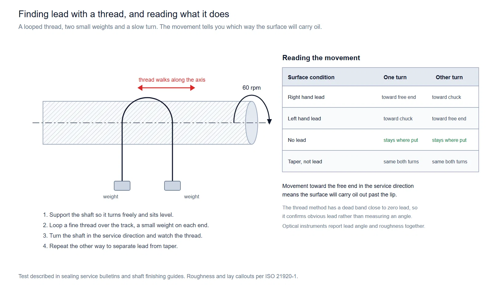
The classic check for lead needs a length of fine thread and two small weights. It appears in crankshaft journal bulletins and in radial shaft seal technical guides, with the same setup in both.
- Support the shaft so it turns freely and sits level, between centres or in V blocks.
- Loop the thread over the seal contact track and let a small weight hang on each end. The weights hold the thread against the surface.
- Turn the shaft slowly by hand, around 60 rpm, in the direction it turns in service.
- Watch whether the thread walks along the axis, and which way.
| Surface condition | Turn in the service direction | Turn the other way |
|---|---|---|
| Right hand lead | thread moves toward the free end | thread moves toward the chuck |
| Left hand lead | thread moves toward the chuck | thread moves toward the free end |
| No lead | thread stays where it was placed | thread stays where it was placed |
| Taper rather than lead | moves the same way in both turns | moves the same way in both turns |
Read it this way: if the thread walks toward the free end when the shaft turns in the service direction, the surface will carry oil out past the lip.
Two limits on the method belong in the record. First, the thread has a dead band; observers report that angles inside roughly ±0.05° leave the thread stationary, which is exactly the band the industry treats as zero. The test confirms an obvious lead and separates right hand from left hand. It does not measure an angle. Second, a shaft that moves the thread the same way in both directions is tapered or has a form error rather than a lead, and rotating it end for end reverses the direction, which is a quick way to tell the two apart. Where a number is needed, optical surface metrology instruments map an area and report lead angle in the same measurement as roughness.
Roughness measurement: direction, cut-off and which Rz you mean
Three details change the number that comes back from a roughness instrument on the same journal.
Measurement direction. ISO 6194-1 calls for shaft roughness to be measured in the axial direction. A stylus travelling axially crosses the grinding marks; a stylus travelling around the circumference runs along them. Roughness measured along the lay reads lower than roughness measured across it, so an axial trace is the conservative one and the one the standard names.
Cut-off length. Roughness is a property of the surface as filtered. The conventional cut-off for the Ra band this application sits in, Ra 0.1 to 2 µm, is 0.8 mm, with an evaluation length of 4 mm. A longer cut-off admits more long wave content and reports a higher Ra for the same surface, so a report that does not state its cut-off cannot be compared with a drawing that does.
Which Rz. In ISO 4287:1997 and later, Rz is the maximum height of the profile within a sampling length. In the older ISO 4287-1:1984 the same symbol meant the ten point height, the mean of the five highest peaks plus the mean of the five deepest valleys, and that definition has been removed from the ISO series. It survives in some national standards, so an inherited drawing that quotes Rz may not mean the parameter an ISO 21920-2 instrument reports. Confirming the definition comes before arguing about a value.
The surface texture standards themselves were restructured in 2021:
| Standard | Status | What it covers |
|---|---|---|
| ISO 1302:2002 | withdrawn, replaced by ISO 21920-1:2021 | indication of surface texture on drawings, including the lay symbol |
| ISO 4287:1997 | withdrawn, replaced by ISO 21920-2:2021 | terms, definitions and parameters such as Ra, Rz and Rsk |
| ISO 4288:1996 | withdrawn, replaced by ISO 21920-3:2021 | cut-off, evaluation length and assessment rules |
| ISO 25178 | current | areal three dimensional parameters such as Sa and Sz |
A drawing in circulation that cites ISO 1302 or ISO 4287 remains readable, because Ra and Rz carried over into the replacement parts with their definitions substantially intact. What changed is the indication syntax and the default rules for filters and evaluation length. A new drawing should cite the ISO 21920 series.
What to put on the drawing
Six items close the gap between a roughness callout and a journal that seals:
- Shaft diameter with the h11 tolerance band, and the nominal diameter the lip is sized for.
- Ra 0.2 to 0.5 µm, with the cut-off and the evaluation length stated next to the value.
- Rz 1.2 to 3.0 µm, so the extreme peak to valley condition is bounded and not only the average.
- The lay symbol set to circumferential, and the word ground written on the texture symbol.
- The condition free of machining lead, plus the lead angle limit you want applied, written as a number rather than left to the standard.
- Hardness and the depth of the hardened zone over the contact track.
Item five is the one usually missing. A drawing that carries item two alone has specified the finish of the surface and not its direction.
What to record when shafts arrive
- Roughness value in the axial direction, with cut-off, evaluation length, instrument and stylus tip recorded.
- Rz from the same trace, so the report shows a peak to valley figure alongside the average.
- Thread test result in both directions of rotation, written as a direction rather than as pass or fail.
- Hardness at the contact track, taken at a point that will not become a leak path.
- Surface condition against the ISO 6194-1 clause 7.3 list: no scratches, scores, pores or spiral marks.
- Process route from the supplier, naming the finishing operation, because the route decides whether lead is possible at all.
Sampling follows whatever plan you already run, and a sampling plan is a risk level rather than a statement about any individual shaft. The value of the record above is that it turns a discussion about a drip into a comparison of numbers and directions.
Failure patterns that trace back to the shaft
| What the service report says | Shaft cause to check first | How to check it |
|---|---|---|
| Slight film of oil at the lip, worse in one direction of rotation | lead running with the rotation | thread test both ways |
| Dry, hard lip with an unusually wide wear track | lead running against the rotation, or a finish finer than the film needs | Ra and Rz measured axially |
| Leak appears on new shafts and clears on a reworked shaft | spiral introduced by belt or hand polishing after grinding | compare the process routes of the two shafts |
| Visible groove cut into the journal | hardness below the 30 HRC floor | hardness check at the track |
| Repeating pattern of marks right around the journal | wheel to work speed ratio held at a whole number | grinding cycle record |
Questions buyers ask us
Does a Ra 0.4 µm reading prove the journal has no lead?
No. Ra is an average of height deviations and carries no information about direction. A surface with circumferential marks and a surface with a helix can return the same Ra. The lead requirement is a separate line in ISO 6194-1 clause 7.3 and needs a separate check.
Can a lead sit inside the tolerance and still leak?
Yes, if the drawing names only a roughness value. The industry lead angle limit of 0° ± 0.05° is not a clause of ISO 6194-1, so a purchase order that references the standard alone has not stated a lead limit at all.
Which direction of lead is the dangerous one?
The helix that opens toward the air side while the shaft turns in the service direction. The opposite helix pushes fluid back into the housing and strips the film, which shows up as lip wear rather than as a drip.
Is the thread test a measurement?
It is a directional check. Its dead band sits around the same ±0.05° that practice treats as zero lead, so it confirms an obvious helix and identifies its hand. An angle needs an optical instrument.
Do we need ISO 1302 or ISO 21920 on a new drawing?
ISO 1302:2002 was withdrawn and replaced by ISO 21920-1:2021, and ISO 4287 and ISO 4288 were replaced by ISO 21920-2 and ISO 21920-3 in the same revision. Legacy drawings that cite the older numbers stay readable, but a new drawing should cite the current parts and state the cut-off and evaluation length.
Is a smoother journal better?
Only down to the bottom of the band. An over polished track below the film thickness the lip needs gives up its oil film, the lip runs hotter and wears faster, and that very fine finish also tends to come from a process that introduces a spiral.
Putting the requirement into your own specification
Shaft lead is unusual among seal failure causes because it is decided entirely inside the grinding cycle and is invisible on the finished part. The two settings that control it, the wheel to work speed ratio and the spark-out time, cannot be inspected afterwards. What can be inspected afterwards is direction, and direction can be checked on any shaft at a receiving bench with a piece of thread and two weights.
The practical sequence is to write the lead condition and a lead angle limit onto the drawing next to the Ra value, to state the cut-off and evaluation length so the number can be reproduced, and to record a thread test result in both directions of rotation against the finished part. That keeps a shaft discussion on measurable ground instead of on the seal.
- Standards and documents referenced: ISO 6194-1, ISO 6194-3, ISO 21920-1, ISO 21920-2, ISO 21920-3, ISO 286-2, ISO 25178, ISO 1302 (withdrawn 2021), ISO 4287 (withdrawn 2021), ISO 4288 (withdrawn 2021), ISO 4287-1 (withdrawn 1984), DIN 3760.
Need help specifying a seal?
Use these checks to prepare your enquiry. Final suitability depends on the specific design and operating conditions.
Check dimensions and design
Provide the shaft diameter, housing bore and seal width in mm. Include the part marking, lip profile or a dimensioned drawing if available.
Describe operating conditions
Share the fluid or medium, operating temperature, pressure and shaft speed. Confirm the material grade against the application.
Verify a replacement
Provide the original part number and photos. Similar dimensions alone do not confirm interchangeability; compare the design and material.