Oil Seal Oscillating Shaft: What ISO 6194-4 Does Not Test
ISO 6194-4 clause 5.3 names four test variables and none of them is swing angle. An oil seal oscillating shaft duty has to be written on the drawing.
Oil Seal Oscillating Shaft: What ISO 6194-4 Does Not Test
ISO 6194-4 clause 5.3 names four test variables and none of them is swing angle. An oil seal oscillating shaft duty has to be written on the drawing.
Short answer
An oil seal oscillating shaft is a shaft that swings back and forth through a fixed angle instead of completing revolutions. ISO 6194-4:2009 defines the performance test for elastomeric rotary shaft lip seals as ten cycles of 24 h. Each cycle holds 14 h at normal operating temperature with normal shaft speed. Then 6 h run at the maximum envisaged temperature with maximum speed. Four hours stopped close it. Swing amplitude appears nowhere in that procedure. Clause 5.3 lets purchaser and supplier agree four variables only: normal operating temperature; normal operating shaft speed; maximum envisaged operating temperature; maximum envisaged shaft speed. A pass tells you the lip held oil while the shaft kept turning. It says nothing about a lip asked to hold oil on a shaft that reverses 1 200 times an hour.
What the dynamic test actually runs
ISO 6194-4:2009 is the third edition, published in 2009. It was confirmed again in 2026. Its abstract runs to two sentences: general test requirements for rotary-shaft lip-type seals, for qualification purposes.
Clause 5.4 sets the run. Six seals go on the rig. Ten cycles of 24 h follow. Each cycle holds 14 h at normal operating temperature with normal shaft speed, then 6 h at the maximum envisaged temperature with maximum speed, then 4 h of shutdown while the machine comes back to room temperature. Running time totals 240 h.
Count the transitions inside those 240 h. Ten stops. Ten starts. Between them the shaft turns the way the rig was built to turn it.
Clause 5.1 holds the machine steady. Shaft speed stays within ±3 %. Eccentricity stays within ±0.03 mm. Test fluid temperature stays within ±3 °C. Fluid volume is at least 750 cm³, with the level set 0.3 d1 to 0.5 d1 above the lowest point of the shaft.
Clause 5.2 asks for the test shaft to sit so that a clean, unused area of its surface is in contact with the sealing element. That instruction presumes new surface keeps arriving. Shafts that return across the same arc never deliver any.
The four variables clause 5.3 lets you agree
Clause 5.3 is where control passes to the two parties. Its wording asks for test conditions that simulate the application, agreed by purchaser with supplier. Then it names them.
| Clause 5.3 variable | Written on the report as | What it leaves out on an oscillating duty |
|---|---|---|
| Normal operating temperature | One temperature in °C | Nothing. Temperature still transfers |
| Normal operating shaft speed | One speed, normally r/min | No amplitude, so no swept arc |
| Maximum envisaged operating temperature | One upper temperature in °C | Nothing. The hot end transfers too |
| Maximum envisaged shaft speed | One upper speed | No reversal rate. No dwell at the ends |
Four slots. Amplitude is not among them. Reversal rate is not among them. Dwell at each end of the sweep is not among them.
Fit a rotary seal to a joint that swings ±20° and clause 5.3 has no field for it. Reports from that rig can be complete. They can be correct. They can still say nothing about the one number that decides how the lip fails.
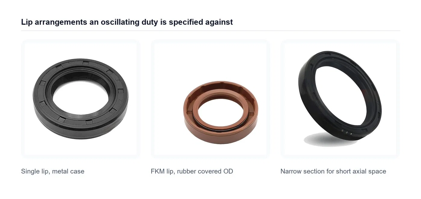
Swing angle decides how much shaft the lip ever touches
Work it out on a 60 mm journal swinging ±20°. One stroke covers 40° of arc, which at the shaft surface is 20.94 mm. A full there-and-back cycle covers 41.89 mm against a circumference of 188.50 mm. On every stroke the lip works the same 11.1 % of the shaft, for the whole life of the machine.
Narrow the swing to ±5° and one stroke drops to 5.24 mm, or 2.8 % of the circumference. Widen it to ±180° and one stroke becomes the full 188.50 mm.
At 10 cycles per minute the ±20° case comes to 25.13 m of sliding per hour. That same 60 mm shaft turning continuously at 100 r/min covers 1131 m in an hour, roughly 45 times farther. Mean surface speed across the swing works out to 6.98 mm/s, or 0.007 m/s. No hydrodynamic feature moulded onto a lip is built to raise a film at that speed.
Reversal count separates the two duties more sharply than distance does. Ten cycles per minute gives 1 200 reversals an hour, which is 288 000 across the 240 h the standard spends on qualification. Clause 5.4 produces 20 speed transitions in that same 240 h. Counted that way, the ratio is 14 400 to one.
| Duty on a 60 mm shaft | Swept share of circumference | Sliding distance per hour | Reversals in 240 h |
|---|---|---|---|
| ±5° at 10 cycles/min | 2.8 % | 6.28 m | 288 000 |
| ±10° at 10 cycles/min | 5.6 % | 12.57 m | 288 000 |
| ±20° at 10 cycles/min | 11.1 % | 25.13 m | 288 000 |
| ±20° at 30 cycles/min | 11.1 % | 75.40 m | 864 000 |
| ±180° at 10 cycles/min | 100 % | 226.19 m | 288 000 |
| 100 r/min continuous | 100 % | 1131 m | 20 |
Every figure in that table comes from s = π × d × (2A / 360) for a single stroke, doubled for a full cycle, then multiplied by the cycles in an hour. Any spreadsheet reproduces it.
What a reversal does to the film
Optical interferometry and numerical work on reciprocating contacts report a film thinner than the film measured under unidirectional motion at the same speed. Starvation is the reason given. Cavitation left behind by the previous pass through the contact persists for a short time after the direction changes, so each new stroke starts on a drier surface than steady running would have given it.
That is the mechanism behind the field signature. Wear concentrates on a narrow track. Torque fluctuates within each stroke. Heat has nowhere to go when the stroke is short, because the only cooling path a lip has is the same oil film that just collapsed.
Speed makes the point numerically. At 100 r/min a 60 mm shaft runs at 0.31 m/s. At 1 500 r/min it reaches 4.71 m/s. Oscillating duty at 10 cycles per minute puts 0.007 m/s on the lip, and the film has to survive a stop at each end of that.
Designers working on oscillating joints describe the same picture from the other end. Small angles near ±10° and ±20° turn up on indexing heads; valve spindles; swing cylinders. Angles approaching ±180° turn up on robot joints, and those positions are commonly specified with a PTFE based primary lip plus a spring energiser rather than an all-elastomer lip. Published sources place the boundary between the two in different places, so treat the angle bands as the opening of a conversation rather than a rule.
Where the wear track lands, and what it tells you afterwards
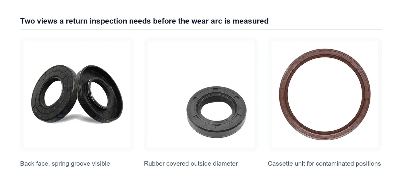
Shafts that only ever rotate show a wear band the whole way round. Shafts that oscillate show a band covering part of the circumference, with unworn surface either side of it.
That difference is diagnostic, and it outlives the seal. Measure the arc. A band 20.94 mm long on a 60 mm shaft is 11.1 % of the circumference and points at a ±20° swing. A band around the full 188.50 mm says the shaft turned, whatever the machine was supposed to do. Large swing rings behave the same way: a 200 mm bearing at ±5° sweeps 17.45 mm, which is 2.8 % of a 628.32 mm circumference.
That measurement also separates oscillation from the two failures usually blamed for it. Runout from a worn bearing leaves a band that runs all the way round and runs deeper on one side. Fitting damage leaves a cut or a rolled lip at one point rather than a worn arc.
Clause 5.5 of ISO 6194-4 asks for the contact bandwidth to be measured once the test ends. Asking for that measurement on a returned part costs nothing and answers the question directly.
The caveat is already printed in the standard
Clause 5.7 sets acceptance. Unless manufacturer and purchaser agree otherwise, there shall be no visible leakage from all six seals, and visible leakage is defined as any wetness on the outside of the seal.
Under it sits a note that matters more than the requirement. Seal performance can be influenced by operating and environmental conditions beyond the scope of this test, the standard says. Oscillating duty is exactly such a condition. Suppliers quoting clause 5.7 quote a clause that flags its own limits one sentence later.
Ask which conditions the reported run used. Ask whether the rig turned the shaft or swung it. Ask for the shaft diameter in mm, the fluid temperature in °C and the speed in r/min, all three of which clause 5.6 expects on the report regardless of duty.
The same committee publishes a reciprocating method
ISO 6194 and ISO 7986 come out of one subcommittee, ISO/TC 131/SC 7. ISO 7986:2026 was published on 2026-10-07 as edition 2, at 24 pages. It replaces ISO 7986:1997, which now stands withdrawn. Its scope covers test conditions and methods for assessing seals used in oil hydraulic reciprocating applications; the title narrows that to rod seals.
So the committee does hold a reciprocating test method. It holds no oscillating one, and ISO 7986 is written for rod seals in hydraulic cylinders rather than for a lip seal on a swinging shaft. Buyers should not reach for it as a substitute. Its existence does settle one argument though. Reciprocating motion is recognised as a class of its own with its own test method, and rotary shaft lip seals are not tested against it inside ISO 6194.
What to put on the drawing and on the enquiry
Enquiry checklists in general use ask for shaft diameter; rotational speed; direction of rotation; whether duty is continuous or intermittent; runout; eccentricity; lubrication. Oscillation appears on those lists as a movement type in its own right, sitting next to reciprocating and rotary. Most of them still give it no number field.
Write the number in anyway.
- Swing amplitude in degrees from centre: ±20°, not "small oscillation"
- Cycles per minute; whether the sweep is sinusoidal, ramped, or held at each end
- Direction of the loaded sweep where the load is not symmetric
- Cumulative rotation over the service interval where the joint also indexes
- Lubricant, and whether the cavity is oil filled or grease filled
- Shaft diameter; its tolerance; roughness in µm; hardness in HRC
Six items. Each one changes what the lip has to survive. None of them has a slot in clause 5.3.
What to ask for instead of a pass statement
Clause 4.2 of ISO 6194-4 already hands buyers a list of declared values to collect before any test begins: material designation and batch number; nominal density; nominal hardness; maximum compression set; maximum mass change after immersion in the test fluid. Those come from the batch rather than the rig, and they travel to any duty.
For an oscillating duty, put three further questions to whoever quotes.
- Has this lip run on a swing rig, and at what amplitude in degrees?
- If it has not, what does the supplier expect to change, and on what evidence?
- Will the test report state the amplitude, or the speed only?
Question three gets answered honestly more often than the other two.
Questions buyers ask
Does a seal that passed ISO 6194-4 work on an oscillating shaft?
It may. The test does not cover the duty, so the report carries no information either way. Passage means six seals ran 240 h with the shaft turning continuously and showed no wetness on the outside.
Is a wider swing easier than a narrow one?
Not in a straight line. Wider sweeps spread wear over more of the shaft and raise mean surface speed, which helps the film. They also drag the lip across fresh surface on every stroke, so debris picked up at one end gets carried to the other. Sources place the practical boundary differently, so state the angle and let the supplier answer against that number.
Should the enquiry give degrees or millimetres?
Degrees, together with the shaft diameter. Together they give the swept arc in mm, which is what the lip actually sees. Writing "about 20 mm of travel" without a diameter leaves the arc undefined.
Does a second lip help here?
On a contaminated joint, yes, for the same reason it helps anywhere else. It adds a dry rubbing contact plus the heat that comes with one. On a short stroke, little oil reaches either lip, so weigh the contamination against the heat before specifying one.
Can the shaft finish stay at Ra 0.4 µm?
It can, and ISO 6194-1 clause 7.3 asks for Ra 0.2 to 0.5 µm with Rz 1.2 to 3.0 µm measured axially. Clause 7.3 also asks for a surface free of machining leads. This second requirement carries more weight here, because a lead that pumps one way while the shaft rotates pumps the other way on the return stroke. Housing dimensions do not change either: clause 7.2 holds the shaft to h11, clause 8.2 holds the bore to H8, and clause 8.3 puts the bore surface at Ra 1.6 to 3.2 µm with Rz 6.3 to 12.5 µm.
Writing the duty back into the drawing
Add a line under the seal callout. Swing amplitude in degrees. Cycles per minute. Lubricant. Whether any continuous rotation happens between swings. Four items, each of them a number somebody can check.
Then ask for the same four on the test report. Where they cannot appear, the report describes a rotary duty. Say so on the purchase order before the parts ship rather than after they leak.
- Standards referenced in this article: ISO 6194-1 (nominal dimensions and tolerances; clause 7.2 shaft tolerance, clause 7.3 shaft surface, clause 8.2 bore tolerance, clause 8.3 bore surface); ISO 6194-4 (performance test procedures; clause 4.2 declared values, clause 5.1 apparatus, clause 5.2 preparation, clause 5.3 test conditions, clause 5.4 test procedure, clause 5.5 post-test measurements, clause 5.6 recording, clause 5.7 acceptance criteria); ISO 7986 (test methods for rod seals in oil hydraulic reciprocating applications); ISO 16589 (seals with thermoplastic sealing elements); ISO 286-2 (limits and fits).
Need help specifying a seal?
Use these checks to prepare your enquiry. Final suitability depends on the specific design and operating conditions.
Check dimensions and design
Provide the shaft diameter, housing bore and seal width in mm. Include the part marking, lip profile or a dimensioned drawing if available.
Describe operating conditions
Share the fluid or medium, operating temperature, pressure and shaft speed. Confirm the material grade against the application.
Verify a replacement
Provide the original part number and photos. Similar dimensions alone do not confirm interchangeability; compare the design and material.